|
|||||||
| Register | Options | Profile | Last 1 | 3 | 7 Days | Search | Today's Posts | Mark Forums Read |
 |
|
|
Thread Tools |
|
#31
 Sat 15 September 2012, 16:38
|
|||
|
|||
|
Well I use Mach3 just because its popular and most folks can help you out with the setup. May I suggest www.vectric.com a very good software base and its not that hard to learn. Solidworks is an awesome program but its a steep learning curve (at least it is for me).
Keep going its the tool in the shop! Cheers Tim#79 
|
|
#32
Sun 23 September 2012, 18:41
|
|||
|
|||
|
ok .. lets keep the updating.
since i found to linear guides extras i will use a couple for the Y slide.   everything looks better with love a some cleaning. the little bearing is from the first pack i found those little ones to the MM, so i keep the big ones for a possible Y axis on a new machine.  my wieght test. 3 pickup tyres complete with rines. no idea why i did this.  ok this is a last time modification. i know is not the best way to keep the table straight but i have 6 legs and the own weitgh of the structure keep it rigit. why i did this. next picture.   i dont have much place to put boards. so make a bed with 4 weels. nothing fancy. and almost costless. i recomend this. under the table is a lot of space. 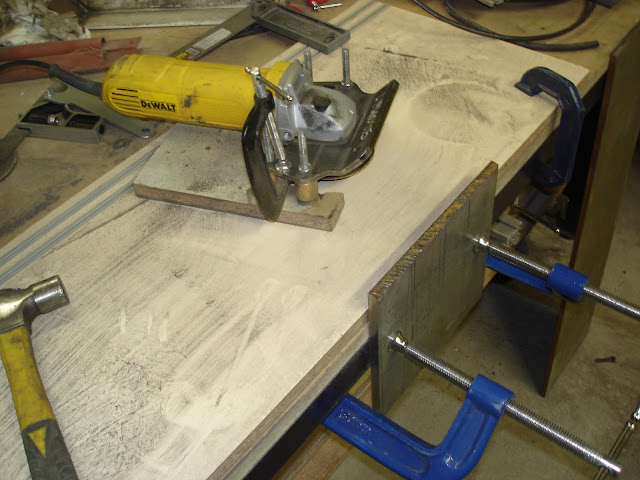 cuthing a 9mm thick piece of metal for the Y slide. just to show that the grinder adaptor is a great tool. iam using a dewalt 818 900w grinder. fits perfect. and is a beast. 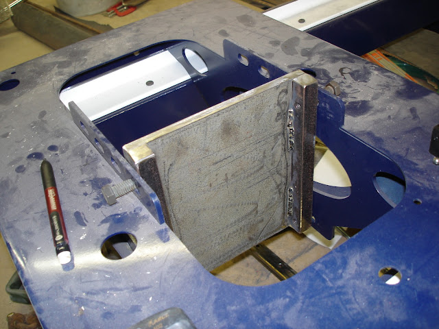 final design.  with the linear bearings. https://lh5.googleusercontent.com/-f...0/DSC00918.JPG presenting the project.   done with the rack screwed. i cut some extra metal to remove some kilos. i did some video so you see how is working. with help of my employee. http://youtu.be/juphC9-TtxI Last edited by zumergido; Sun 23 September 2012 at 18:45..
|
|
#33
Mon 24 September 2012, 01:15
|
|||
|
|||
|
I dont know if this has been mentioned before, but your cross members under the table appear to be mounted incorrectly. I see you have them "flat" with the broad face fixed to the bottom of the main beams, they should be mounted "vertically" with one of the narrow faces against the bottom of the main beams - this would be much stronger and you table would defelect less.
Why is the Z plate so long?
|
|
#34
Mon 24 September 2012, 05:56
|
|||
|
|||
|
hi Alan.
yes they are more efective vertically. i put them like that becouse i bolt them with 2 bolts and found more space that way, not a big problem if you sum 8 pieces.. and the maximun weight is some boards.
|
|
#35
Mon 24 September 2012, 05:59
|
|||
|
|||
|
Hi Fernando
Your machine might benefit from some more cross bracing for the legs. Cross bracing is most effective when it goes across the full length of the diagonal. The plans show an effective and cheap way to brace the underside of the table. The reason bracing is required is that the load on the CNC machine is not static and downward like a heavily loaded kitchen table might be. As the heavy gantry, Y car and Z axis move around they will set up oscillations that need to be controlled. The faster these components move the more inertia they have. So despite the machine feeling solid in a static position, a moving machine may require extra stiffening. Each single additional cross brace you add will provide substantially more rigidity in the table base. Regards Ross
|
|
#36
Fri 05 October 2012, 09:10
|
|||
|
|||
|
ok its alive.
i got the gears and the first thing i do is make it run. just wired to the computer using the first cable i found. i didnt find the shield cable for the spindle. so i was a little worried about the interference. at this point i dont see any loose step. do a comparator test and was succefull. now have to square the gantry, finish some cables, do cable chain for the gantry, conect limits, conect the inverter to mach3, and learn how to use all the software. i do a rs232 modbus that have 7 output relays, 10 digi inputs, pwm out, mpg support, and some analogics inputs. i will use the lpt port only for the motors. http://www.youtube.com/watch?v=G-waH...&feature=g-upl
|
|
#37
Sat 27 October 2012, 21:17
|
|||
|
|||
|
is anyone use serial modbus io cards
i have made this one. just buy the board and the pic. configure some relays to control lights and inputs to control start, stop, estop, home sensors, probe. works good. just left the lpt port for motors only. what can be a good setup for lights and swiches? what are the fundamental setup. considering that this cards cost like 30 uss and you can put one on each serial port usb serial works great. the hard part is program the brains on mach 3 the brain interface is very limited. its desing by a guy here in argentina.  tnks. iam having some trouble doing circles. they are not exactly round. have to do more tests to bring the problem to forum.
|
|
#38
Sat 10 November 2012, 18:59
|
|||
|
|||
|
doing the reduction system.
doing some experiment of how to do the pulleys. will use 5M gates powergrip. i was thinking on 15mm but the 9mm are really strong. since i dont know anything about pulleys i found this page very usefull http://www.fulong-drivingbelt.com/entable/pro_07-2.htm using corel draw and vectric i did a test on aluminum that have a error on calculation. then a fix it and do it on acrilic to know how big the belt have to be. its the first time i do something like this what do you think?  i dont have a 3.12 mm drill bit so i use 3.25 mm for the tooth.  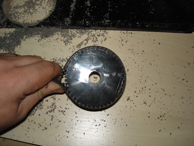 have to see very close to the 0.13mm gap. i still belive they will not have any backslash  i made a 45 and 15 tooth pulley. just to test. final pulley will be on aluminum cheers
|
|
#39
Sun 11 November 2012, 03:28
|
|||
|
|||
|
That is cool.
|
|
#40
Mon 12 November 2012, 10:59
|
|||
|
|||
|
I'll have to keep this method in mind, thanks for sharing
|
|
#41
Sun 18 November 2012, 15:49
|
|||
|
|||
|
Fernando, si no funcan acordate que tengo cortadas laser las reducciones modelo castone, las poleas, las correas reforzadas y los rulemanes con labio.
Pablo
|
|
| Register | Options | Profile | Last 1 | 3 | 7 Days | Search | Today's Posts | Mark Forums Read |
| Thread Tools | |
|
|
 Similar Threads
|
||||
| Thread | Thread Starter | Forum | Replies | Last Post |
| Had a transformer built - Buenos Aires, Argentina | PEU | Construction started, but not cutting yet | 231 | Thu 17 March 2011 18:36 |


