|
#31
 Thu 18 February 2010, 16:01
|
|||
|
|||
|
Yep, propane uses Kiing Copper!

|
|
#32
Thu 18 February 2010, 21:15
|
|||
|
|||
|
If your out in the country far enough to have propane you probably are on well water, when I checked into those units a couple of years ago they told me that I shouldnt get one cause our water was too hard, and I run through 2 big filters and a softner before it gets to the water heater.
|
|
#33
Sun 21 February 2010, 11:55
|
|||
|
|||
|
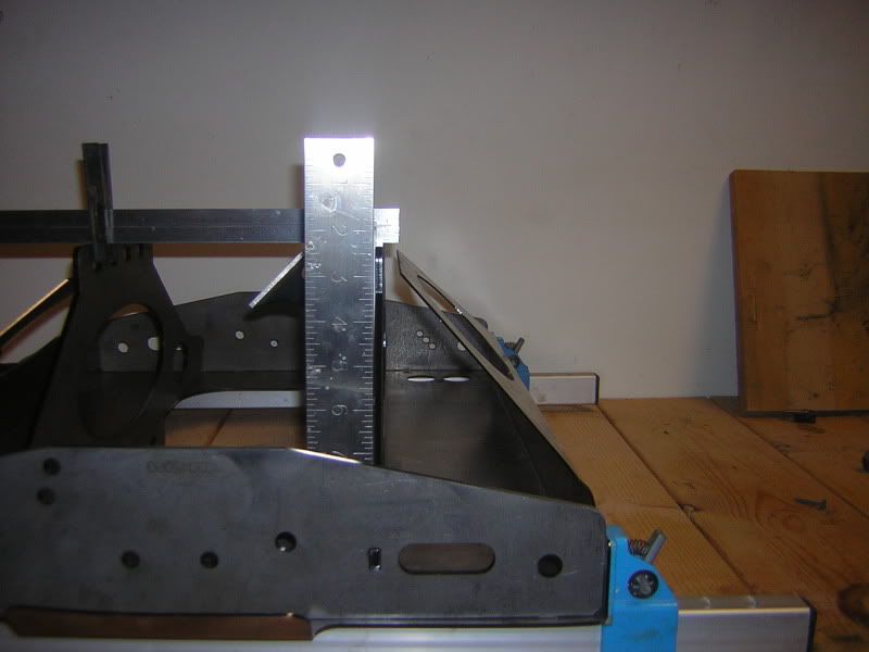
Parts have started to arrive so I decided to work on the Y-car while I wait for the rest of my control parts to get here. I'm a little worried about where #10 30 422 welds to 10 30 455. 10 30 422 is under-bent leaving a gap of about 10 mm (7/16")on one side and 6 mm on the other. I'm trying to decide if I should just force it down, tack it and then take a torch to the bend to relieve the stress or should I just try to get someone to re-bend it.
|
|
#34
Sun 21 February 2010, 12:04
|
|||
|
|||
|
Bum,
10mm for that part doesn't sound like a issue at all, we had the same... It's metal it can bend..., so I would tack weld it in place and then make final welds according to scheme. Ries
|
|
#35
Sun 21 February 2010, 12:15
|
|||
|
|||
|
Just "force" (push) it down and weld. Don't worry about heat treatment afterwards.
|
|
#36
Sun 21 February 2010, 12:18
|
|||
|
|||
|
Thank you for the quick replies. Back to work...

|
|
#37
Sun 28 February 2010, 15:01
|
|||
|
|||
|
Well I got my Y-car welded up and primed waiting to go pick up my steel for the table tomorrow. I got my motors,drives,power wired up to test. I get green lights on the drives and the motors lock up when powered up but the computer I ordered hasn't arrived, so no movement yet.
 Ive been searching around for wire and I'm wondering if there is a reason (other than the work of added connections) for not using high flex cables in the cable chains only. I was thinking maybe it would be possible for plug connections at each end of the cable chain and eliminate the need for so much high dollar wire.
|
|
#38
Sun 28 February 2010, 20:45
|
|||
|
|||
|
Bum,
It is not mandatory to use high flex cable. You can have any screened cable as long as you conform to the minimum allowable bending radius stated by the manufacturer. There are no real space restrain in MM design.
|
|
#39
Mon 01 March 2010, 16:29
|
|||
|
|||
|
Thanks Ken
My motors Are Turning. I'm so relieved.
|
|
#40
Mon 01 March 2010, 20:18
|
|||
|
|||
|
Turning motors! Well done!
|
|
#41
Mon 01 March 2010, 20:37
|
|||
|
|||
|
Congrats with the kitchen table project
 We need to see some pictures though  Ries
|
|
#42
Mon 01 March 2010, 21:17
|
|||
|
|||
|
I'll get some pictures taken as soon as I figure out where my kids hid (lost)the camera.

|
|
#43
Mon 01 March 2010, 21:30
|
|||
|
|||
|
Great, looking forward to it !
|
|
#44
Sat 06 March 2010, 07:15
|
|||
|
|||
|
I finally got out to the Steel salvage yard to dig around for what I need. I managed to find suitable steel for everything but the rails and the gantry. It'll take some clean up before paint but a good deal at $ .45 a lb. My son was nice enough to haul it all home in his Jeep there.
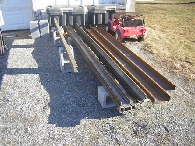 820 lbs there. Plus some tubing I already had. 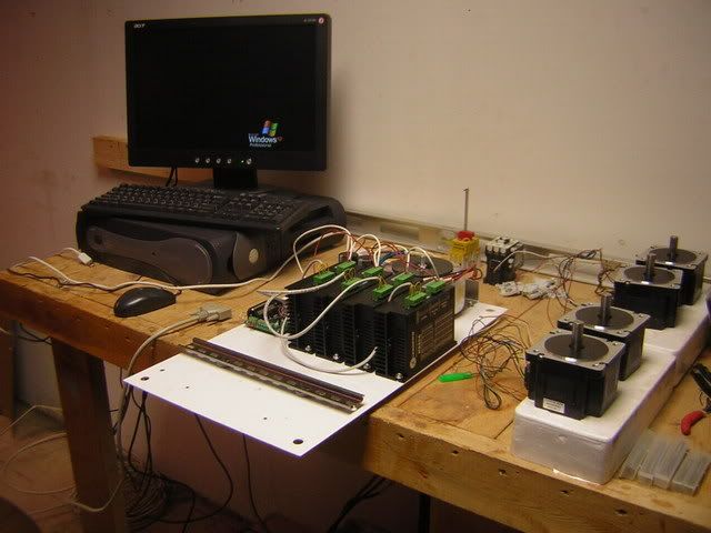 Figuring out how to cram all this stuff into this box. 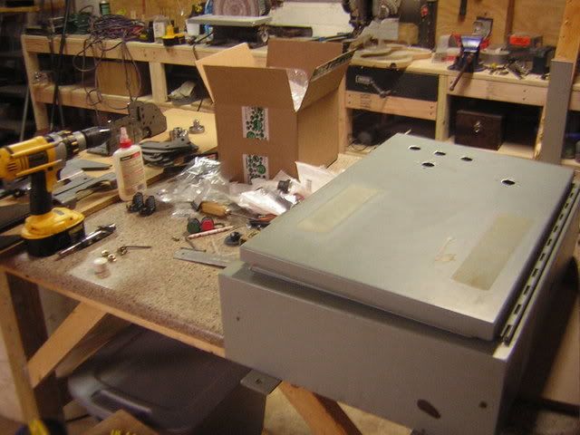 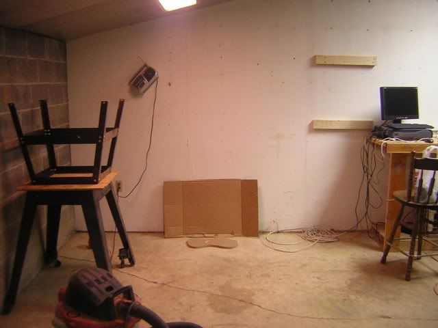 Future home of my MM
|
|
#45
Sat 06 March 2010, 08:12
|
|||
|
|||
|
Hey « Bum » !!?
Good luck on this build. Envy you as your sun sure look to be quite helpful . These jeeps can really haul .  Amicalement, Robert
|
|
#46
Sat 06 March 2010, 10:09
|
|||
|
|||
|
You need a bigger radio on the wall once the MM starts cutting
|
|
#47
Sun 07 March 2010, 16:49
|
|||
|
|||
|
I learned a couple things today.
#1 Working on steel is sloooooow going. #2 I'm not very good at steel work. I did manage to make some progress though. 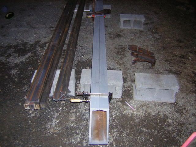 Rails are cut and laid out. 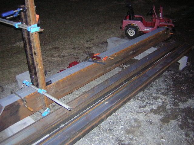 I got the legs cut and drilled and the weld plates cut and drilled.(which are being used as spacers at the moment) I got one set of legs squared up and started to tack them in place when I ran out of Argon. 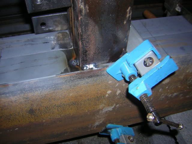 I'm not a very good welder but I should be able to get this together. Tomorrow I'll drill the bottoms of the channels and get the legs finished up.
|
|
#48
Sun 07 March 2010, 17:09
|
|||
|
|||
|
Bum: Looking good. Keep it up and thanks for the pics.
Joe
|
|
#49
Sun 07 March 2010, 20:35
|
|||
|
|||
|
Your welding looks fine to my eye. keep up the work.
One tip, welding WILL deform the steel, don't weld more then 40mm or 1.5in in a go, helps taming serious metal deformation.
|
|
#50
Mon 08 March 2010, 16:24
|
|||
|
|||
|
Made a little progress today. Got the holes drilled and tapped for cross supports and started welding everything together.
I spent most of the day chasing that little guy away from my work area. He loves tools but is too young to understand the dangers and grabs anything in sight, So I have to flip the breaker for the Welder when I want to use it, then if I'm going to set down the torch, turn the breaker back off. Plug in Grinder to use, then unplug. etc. 
|
|
#51
Mon 08 March 2010, 18:13
|
|||
|
|||
|
Alway good to be safe!!
|
|
#52
Mon 08 March 2010, 18:56
|
|||
|
|||
|
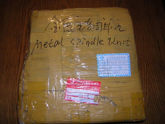
Spindle arrived today. I was wondering why it took 2 weeks for them to ship this out. After seeing all the tape on the packaging they clearly needed all 2 weeks to get it wrapped up.
 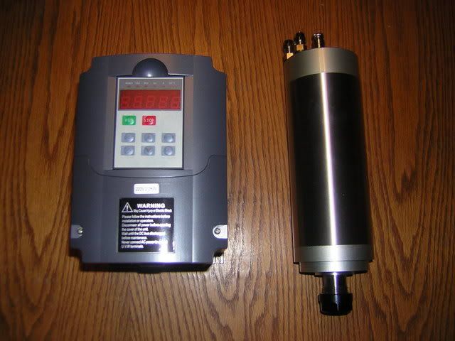 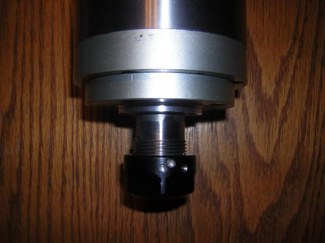 I wonder why these holes are drilled on the collet nut? balance?
|
|
#53
Thu 11 March 2010, 06:24
|
|||
|
|||
|
My Doctor gave me the OK to go back to work yesterday
 so the progress on my MM will be slowed to weekend work. But now I'll be able to afford the bigger radio for the wall. so the progress on my MM will be slowed to weekend work. But now I'll be able to afford the bigger radio for the wall. I should be able to finish up my table this weekend depending on rain. Maybe I'll get enough done on it to get my thread moved to construction started I should be able to finish up my table this weekend depending on rain. Maybe I'll get enough done on it to get my thread moved to construction started Last edited by SumBum; Thu 11 March 2010 at 06:53..
|
|
#54
Thu 11 March 2010, 16:19
|
|||
|
|||
|
Hi Bum
Just a quick suggestion about your planned placement of the stepper drivers while you are still in the design phase. The slotted face of the driver is also a heat sink. If you were to put that against the plastic backplate of the control box it would limit the heat transfer from the driver. A (slightly) raised alloy plate heat sink similar to the one Gerald uses for the Gecko drives might also work for you if there is enough depth to the control box. Regards Ross
|
|
#55
Thu 11 March 2010, 16:47
|
|||
|
|||
|
I mounted them that way so 2 fans will blow air along the fins of the heat-sinks. It may not be ideal but Space is limited in this box.
|
|
#56
Thu 11 March 2010, 17:12
|
|||
|
|||
|
H Bum
That is a good practice as you suggest, please refer to my build thread and you will see that I have used a similar driver configured as you have with two fans blowing along the face of the driver. The bracket for the fans is made of a simple piece of alloy angle with a few pieces taken out with a hole saw. One issue with my design is that the fans blow the rising hot air back down, but this was a case of what fitted best and stayed clear of the wires. The slotted alloy base of the driver will retain heat unless it is given a path to escape (the plastic back plate is acting as an insulator). Mounting the drivers on an alloy plate raised say 20mm above the plastic backplate will significantly increase heat dissipation. Your fans can blow between the plate as well as over the drivers to get the best of both cooling scenarios. Regards Ross
|
|
#57
Thu 11 March 2010, 17:43
|
|||
|
|||
|
I see what your saying. The backplate is steel in my box and raised about a 1/2" from the box, so I thought the dissipation through the steel plate would be adequate when combined with the fans.
|
|
#58
Thu 11 March 2010, 17:49
|
|||
|
|||
|
Apologies Bum, the photo looked like the plate was white plastic, so the steel backplate you have chosen is of course very suitable. Well I'm off to the optometrist for a new pair of specs !!
Regards Ross
|
|
#59
Thu 11 March 2010, 17:56
|
|||
|
|||
|
I have a fan controller from an old gaming rig that has 4 temp displays on it. I think I may throw it in this computer and put a sensor on each driver, so I can monitor each one individually from the computer.
|
|
#60
Thu 11 March 2010, 18:01
|
|||
|
|||
|
Quote:
|
 |
|
|
 Similar Threads
|
||||
| Thread | Thread Starter | Forum | Replies | Last Post |
| 20' long table, 5HP spindle - Port Aransas, USA | skypoke | MechMates already cutting | 42 | Sat 09 July 2011 18:07 |
| Mech Mate build - Philadelphia, PA | jammer3808 | Construction started, but not cutting yet | 2 | Sat 01 August 2009 05:39 |
| Upgrading the vBulletin software that runs this forum | Gerald D | Archives | 54 | Mon 20 July 2009 03:26 |
| Water Cooled Spindle Connections - Connecting the Spindle | waynec | 50. Toolheads | 32 | Fri 19 June 2009 12:31 |
| Upgrading a ShopBot PRT - Newman Lake, WA | mtgstuber | Construction started, but not cutting yet | 13 | Sun 11 November 2007 11:21 |


