|
#121
 Fri 26 June 2009, 13:05
|
|||
|
|||
|
Responsibility accepted .... now back to the skate plate.

|
|
#122
Thu 02 July 2009, 23:55
|
|||
|
|||
|
Hello,
I have been reading all your replies to the interesting topic of the skate design. I am just up to the stage of building the skate to grind my rails, I have cut them to the correct height (what a horrible job, 3 hours to cut 4 rails, I am glad that part is over!!!!). I would like to contribute some ideas to the discussion!! I have tired to incorporate all the ideas so far from Gerard, JR and the rest of the people and build on the existing structure/design philosophy. The design is addressing the issue:-
I have added a bearing support at each end of the skate which is fixed by 4 csk screws. This lowers the skate to 1.6 mm above the rail. A 7 mm height boss has been turned on top to accept a handle. My Hitachi handle has a M10 thread but adjust to suit your handle. The axle is held in place by 2 x M3 set screws adjusted from the top. Bearing is 6001 to match the other bearings. With the handles in this position, it keeps most of the forces low and directly on the top of the rail thus minimizes the twisting action if the handles were positioned off to the side of the skate. The rotation of the grinding head was an interesting problem. I have split the bottom plate into 2 new plates. I hope you can see how this will work. The bottom plate fixes the position of the skate to the rail. The pivot plate and the existing motor plate are used to rotate the disc 18 deg in either direction with respect to the rail. This 18 deg could be changed easily if needed. The bottom plate has 8mm diameter pivot stub 6 mm long which the pivot plate rotates on. The pivot plate has 2 threaded holes with 2 x M8 thread rods which pass through to the bottom plate and to the motor plate. The angle can be adjusted first, then locked off by 2 nuts on the threaded studs. The forward and back position can be adjusted by the 2 x M3 bolts in the Motor plate and then locked off by another 2 x M8 nuts. The angle of the grinding head and the forward and back can be adjusted independently or independently locked in position. I have not done an interference check when I rotate the pivot plate to the max angle but I think the disk opening may have to be changed a bit and the 4 bearing support bolts underneath the skate may have to be changed to studs (maybe). I hope these ideas might spark some other ideas! Cheers Chris
|
|
#123
Fri 03 July 2009, 00:28
|
|||
|
|||
|
Chris
Interesting proposals, question regarding the height of the skate above the rail (given as 1.6mm) Will that still allow enough space underneath to fit in two bearings on a bush without the bearings fouling on the inside corner radius? 18 deg of pivot is way more than you need, 2-3 deg will be more than sufficient, this may be adding complication and extra components where it is not required. I found with the standard skate there was sufficient play in the bolting arrangement to give me enough "twist" on the mounting to grind with minimal glazing.
|
|
#124
Fri 03 July 2009, 09:18
|
|||
|
|||
|
Skate
I dont think that glazing is a problem with the design, as with most types of surfacing the main objective is to keep your grinding stone as flat as possible. Just keeping the skate in motion will prevent glazing of rails.Handles would be a nice option but the skate was designed to make a set of vee rails for a home build with limited tools. I think that the skate fits its purpose. If the skate is changed much more it will take more time to make your skate, than it takes to just grind your rails.
|
|
#125
Fri 03 July 2009, 13:12
|
|||
|
|||
|
Leo
The glazing is not on the rail, but on the grinding disk, after a while it stops "cutting" and just tends to glide over the steel, tilting the skate so the initial grinds are with the leading edge of the disk minimises this. When the profile is almost complete, the grinder is adjusted so the disk is flat on the face for the final polishing
|
|
#126
Mon 13 July 2009, 12:06
|
|||
|
|||
|
Like most things, the second time around will be easier.
I finished grinding my rails. Here's what I did; First, I attempted to cut the rails to height with a cutting disk in my grinder. My hand-me-down grinder would not allow the thin disks to cut flat. They had roughly 1/16" of runout at the cutting edge, thus my kerf was 1/8" +. That didn't work. I looked around for an affordable grinder which would fit the skate. No luck, so I bought a steel cutting circular saw. Once I got the fence adjusted right (the front ever so slightly wider than the rear) they cut the rails nicely and quickly. The first couple of rails have some low spots. I welded up the dips with a small wirefeed welder to bring the overall height to 30mm or so. I was worried that the rails would warp as a result, but this hasn't been a problem. I then went back to my grinder and surfaced the rails to eliminate the saw marks (and flatten the welds) using a thick flat disk (which did run true on my grinder). Now they were flat, smooth and the right height. Then to the skate. I found that if I tweaked the long 5/16" adjustment bolts slightly to assure that the grinding disk contacted the rail only at the circumference of the disk, glazing was minimized. Once it was adjusted properly, I found that there were only two significant frustrations; a) because two of the holes for bearing axles was so close to the bend, the bearing axles were not exactly parallel, so I could not adjust all the rock out of my skate. b) the 1/2" height adjusters. I could not find brass or hardened stainless bolts locally, so I used steel. They had a high degree of friction and I found that they would stick to the rail frequently. 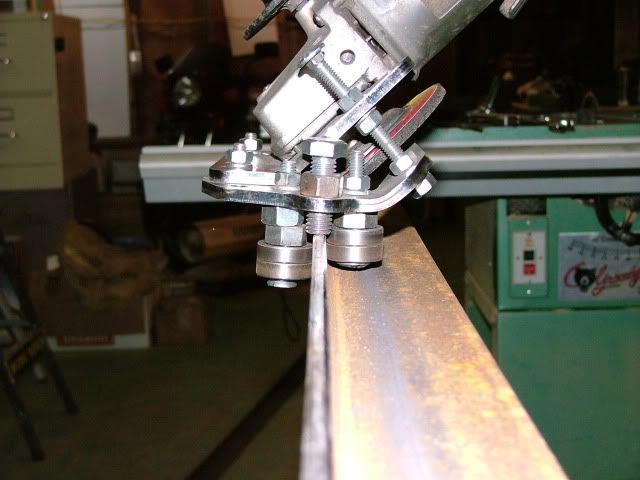 From that experience, I think that the bearing idea is a good one. Besides, the bearings come in packs of 10, and only 8 are required to guide the rail.
|
|
#127
Mon 13 July 2009, 18:41
|
|||
|
|||
|
Now may be a good time to post these. I need to change the cap screws to button heads. It will skew way more than is needed. It is very easy to adjust and fine tune.
|
|
#128
Mon 13 July 2009, 20:06
|
|||
|
|||
|
Cool! I like it.
Something which would also be cool is to set up the long angle adjustment screws so that they don't bolt through both upper and lower pieces, but bolt through the upper and simply ride on the lower. In this way you could still fine tune the v-angle, but adjust the depth of cut more easily.
|
|
#129
Mon 13 July 2009, 20:16
|
|||
|
|||
|
Jeff, not sure I'm completely following what your saying but the way I see it, the 2 plates need to be bolted together securely. Thanks
Last edited by J.R. Hatcher; Mon 13 July 2009 at 20:24..
|
|
#130
Mon 13 July 2009, 20:22
|
|||
|
|||
|
May I make a suggestion. Try removing the extra nut so the bearings riding the sides of the rails are the same height. The way they are offset allows the skate to rock and creates a problem when grinding the opposite side. IMHO
|
|
#131
Mon 13 July 2009, 22:59
|
|||
|
|||
|
Yes, I think you're absolutely right about the extra spacer... in retrospect it was unnecessary and counterproductive. I had to do a fair amount of searching the forum to find a photo/drawing of how they were supposed to be configured. Unfortunately, what I found first was a concept sketch... that I misinterpreted.
http://www.mechmate.com/forums/attac...1&d=1193289275 The two front bolts on your skate hold the two plates together pretty securely. If the upper skate plate was bent slightly less than 45°, the two back (long) screws would only have to hold the plates apart at the proper angle. Since your new bearing equipped skate uses the relative position of the two plates to adjust depth of cut (instead of the 1/2" bolts in the V1 skate) it would be nice to not have to loosen the back screws (and possibly lose the 45° relationship each time DOC is adjusted. BTW, how are the bearing axles secured? Tack welded? Last edited by lumberjack_jeff; Mon 13 July 2009 at 23:12..
|
|
#132
Mon 13 July 2009, 23:22
|
|||
|
|||
|
It is looking good JR! I am busy assembling mine. Will post photos soon.
|
|
#133
Tue 14 July 2009, 05:33
|
|||
|
|||
|
"BTW, how are the bearing axles secured? Tack welded?"
That is correct they will be tack welded right at the end of the axle, on the top of the plate (1st picture). The bottom of the axle will be flush with the bottom of the plate (2nd picture). If anyone needs a special picture just let me know sometime today, it's easy to take right now. Thanks Johan I'm looking forward to your pictures.
|
|
#134
Tue 14 July 2009, 06:10
|
|||
|
|||
|
JR,
Once again, elegant solution. A neat find at the local Lowes. I found in the furniture hardware aisle 5/16" socket head flush (like an elevator bolt) head. Only about 3/16" flat head height. That shaft...is it an "off the shelf McMaster pin, dowel, shaft, etc....or is it a machined item? Thanks for your contributions. Sean
|
|
#135
Tue 14 July 2009, 06:34
|
|||
|
|||
|
JR,
Are you making another machine? Or maybe you have worn out your old rails on all those boat hulls? 
|
|
#136
Tue 14 July 2009, 06:40
|
|||
|
|||
|
Sean, some of the fancy headed screws/bolts cannot be fully tightened from driving their heads - they need a nut on the other end and the nut is tightened to develop the full load. The countersunk below is one of the worst:
The head has too much friction inside the cone of the CSK and the allen key/wrench hole is smaller than normal for that thread size.
|
|
#137
Tue 14 July 2009, 07:54
|
|||
|
|||
|
"The head has too much friction inside the cone of the CSK..."
That never occurred to me before but it makes sense. An R8 arbor in the head of a vertical mill is basically held in place through friction and it has a similar cone shape. Man, I've learned a lot on this forum.
|
|
#138
Tue 14 July 2009, 09:31
|
|||
|
|||
|
I used those countersunk cap screws, but machined most of the cone away to produce a very low head fastner - there is not that much stress in this application to worry about the loss of strength.
see how compact the complete assembly is.
|
|
#139
Tue 14 July 2009, 13:47
|
|||
|
|||
|
Sean, I turned the shaft down from .5" to 12mm + enough for a press fit, it's 1" long and has to be tapped into place. Good idea on the bolt, I'll machine about half the head off a 8mm bolt.
Heath my plans are to build another machine..... when??? don't know exactly. My rails don't show any signs of wear whatsoever. Alan I also like your solution, good idea.
|
|
#140
Tue 14 July 2009, 17:51
|
|||
|
|||
|
Alan, thats what the bolts look like.
Gerald...correct as always! I cant wait for my next machine! It's like an addiction now.
|
|
#141
Sun 26 July 2009, 03:24
|
|||
|
|||
|
Here are pictures of my skate with JR's modifications and other suggestions.
I used M4 screws to keep the bearing shafts in position. It might be easier to drill and tap into the bearing shaft as shown in the direction of the red line. The dxf will have to be adjusted to move the raduis away a little bit so that one can drill into a flat surface. I did not have a M10 tap for the grinder handles, so I tack a M10 Nut in position. It lifts the bottom of the handle up so that it doesn't interfere with the top plate adjustment. I still need to test it.
|
|
#142
Sun 02 August 2009, 06:54
|
|||
|
|||
|
Johan I like your guard idea. Will you please send me the drawing of the lower plate, I would like to suggest a small change. Thanks
|
|
#144
Sun 02 August 2009, 08:29
|
|||
|
|||
|
Johan,
That is one neat grinder.
|
|
#145
Sun 02 August 2009, 09:22
|
|||
|
|||
|
Johan is discussing the grinder in his own build thread.
|
|
#146
Sun 02 August 2009, 09:55
|
|||
|
|||
|
Quote:
|
|
#147
Sun 02 August 2009, 11:06
|
|||
|
|||
|
Quote:
 . So Gerald I like your guard idea, will you please send the dxf I have a suggestion. . So Gerald I like your guard idea, will you please send the dxf I have a suggestion.
|
|
#148
Sun 02 August 2009, 11:18
|
|||
|
|||
|
I didn't keep that drawing, it was just a quick rough idea that can be refined. Maybe the guard can even come from the other plate . . . . .
|
|
#149
Sun 02 August 2009, 13:14
|
|||
|
|||
|
Thanks Gerald. Johan if you have the drawing .......................
|
|
#150
Sun 02 August 2009, 23:40
|
|||
|
|||
|
I will post the drawing some time today.
Gerald, do you suggest I post all my skate developments here instead of my build thread?
|
 |
|
|


