|
#91
 Tue 21 December 2010, 00:09
|
|||
|
|||
|
Congrats on the new addition, to you and the wife.

|
|
#92
Tue 21 December 2010, 05:23
|
|||
|
|||
|
Congrats!
|
|
#93
Tue 21 December 2010, 05:31
|
|||
|
|||
|
Congrats on the new baby !!!
|
|
#94
Tue 21 December 2010, 09:37
|
|||
|
|||
|
Congraulations

|
|
#95
Tue 21 December 2010, 10:51
|
|||
|
|||
|
Congratulations. Looks like in the future he is going to have a lot of cool toys/tools.

|
|
#96
Wed 22 December 2010, 03:01
|
|||
|
|||
|
Thanks and ... more questions
Thanks for the well wishes. I can see wooden toys in his future.
I'm currently grinding rails but don't know when to stop. I remember somewhere that the flat at the top should be ~1mm. So I just gradually sand away using progressively finer grits until the flat is 1mm and then the rails are done?
|
|
#97
Wed 22 December 2010, 03:32
|
|||
|
|||
|
you can stop when you get near 1mm wide edge, & no further work required... Mine is 1.5mm wide...
|
|
#98
Thu 23 December 2010, 02:34
|
|||
|
|||
|
Hi Red
Congrats on the new bub, he looks like a beauty. Start those surfing lessons early. Regards Ross
|
|
#99
Thu 23 December 2010, 03:21
|
|||
|
|||
|
Thanks Ken.
Ross your "baby" looks fine too.
|
|
#100
Sat 25 December 2010, 05:29
|
|||
|
|||
|
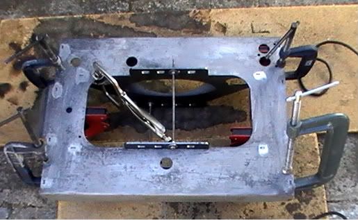
Red's guide to Rail Skate and grinding (definitely not the best way, but OK)
Despite going through all the posts I could find that mention the grinding skate, I still struggled a bit with it. I put it together as in the pic below. (I had to weld to fill in the holes for the grinder screws)
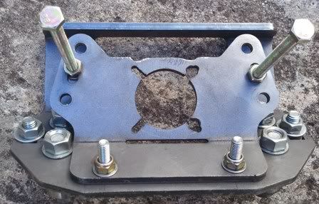 I drilled out the 4 holes for the bearing "axles" to 13mm under the assumption that a 12mm bolt was the correct axle. I used washers to get things in the right place and bearings free running. Later I noticed that the bearing eccentrics should be used as axles. Minor significant point. I was able to get the beasings a tight fit on the angle because of the oversized holes, but the eccentics would have definitely been a better route. I used bolts with washers at each end of the bottom plate for height adjustment. I see that some have used bearings here but I did not have the wherewithall to do this. I drilled in the centre hole of the top plate and bolted the top and bottom plates together. I also used 2 long bolts as supports between the top and bottom plates. But when I put the angle grinder in place and slid the skate onto the angle I could not get the sandpaper to meet the steel. I don't know whether the shaft on my De Walt grinder is shorter than most (it's the same length as the $40 special I bought yesterday), but I could not adjust things to get the paper into a grinding position. I dissembled and drilled the near hole in the top plate. This gave me the adjustment I needed to get the sandpaper to meet the angle. But I could no longer use the long bolts as supports because the holes in the top and bottom plates were no longer aligned. I moved the long through bolts to the top plate only and set them up as handles. The handles proved invaluable later. I struggled to fine tune the adjustment of sandpaper contact with the angle. It seemed that the top plate could be moved to bring the paper closer and the height adjustment bolts could be lowered to make a difference too. Regardless what I did I was always sanding with the outer edge of the disk. I eventually settled for having the paper touch the angle when the skate was in place. This seemed to remove a reasonable amount of steel without overloading the grinder (but there was significant load nonetheless). The grinder pulled itself in one direction. Not by design, I might add.  Because the skate is 6mm thick there was only little thread holding the grinder to the skate ( I couldn't source longer screws of the correct thread). I ground the skate thinner at the screw fixing points so that more thread would hold on the grinder. Two of the 4 screws stripped in the course of the grind. Because I used standard M12 bolts as axles for the bearings, the bearings rode quite high on the angle. Round headed bolts would have been better. There was a little wobble in the skate on the angle. I standardised by ensuring that the far side of the skate was "down" as this produced the requisete angle. The whole affair looked like so: 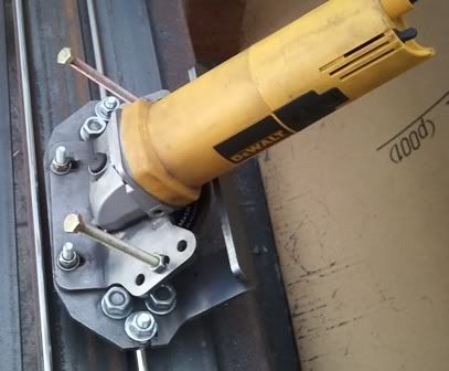 I used a second angle so that the skate was equally supported on both sides. I was really worried when making the first few passes whether I had the angle right because the vee bearings did not seem to sit quite right. This problem disappeared when I sanded more away and the flat bit on the top of the rail approached 2mm. I didn't lubricate but was careful to keep pressure on the skate via the "handles" to overcome any stickiness. I also sanded the rail flats before starting to ensure a smooth (and level!) surfaceThe skate seemd to stick more as the rail top got narrower. I also rotated the height adjustment bolts periodically to prevent a deep groove being worn by the rail top. The rails are one part of the build that worries most people. I reasoned that the worst I could do would be to ruin some angle, burn out a grinder or end up with a wobble rail. It turned out not too bad and the results look fine. I did almost fry my grinder, though. I took to making a dozen passes and then doing something else for a while (next episode) so the grinder could cool down. I took a day off from Grinding. After all it is Christmas Day and peace reigned in the neighborhood. Merry Christmas!
|
|
#101
Sat 25 December 2010, 05:52
|
|||
|
|||
|
Hi Red
Two high tensile bolts on the skate were it slides on the top of the rail will significantly reduce the wear or slotting you are experiencing. Candle wax is a good dry lubricant to reduce sticking of the skate as it slides. Regards Ross
|
|
#102
Sat 25 December 2010, 18:05
|
|||
|
|||
|
Thanks Ross. I had the candle wax ready, but the sticking wasn't bad enough to warrant its use. High tensile bolts would have been good, but the slotting also isn't serious (more like scratching).
|
|
#103
Sat 25 December 2010, 18:41
|
|||
|
|||
|
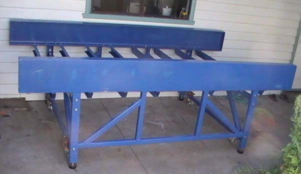
Repairing bad bad welding prior to painting
While I was waiting for the grinder to cool down between bouts of rail sanding (and to give the neighbors some peace!) I set on the journey of painting the base so I could assemble and level it ready to drill and tap holes for the rails. I originally intended to drill the beams unassembled, but there is a curve in one beam that I either built into the base table or corrected out. I'm not sure which, so I have to erect the bolt together base table so that I can be sure of getting the rail holes drilled in a straight line according to the beam, curved or not.
I have 4 ladder frames that bolt together to recive the beams bolted on. The ladders were the first welding I had done. While they held together the results were not only ugly, they were not always sound. I started to grind back the lumps of welding and clean up the spatter and then re-weld with everything clamped tight to limit distortion. One of the problems for a beginner welder in using box steel for the frame is that the box has a fillet at the corner, so there is always a gap that needs to be filled ("you can't weld air" is one of the first things I learnt!) before a butt join can be done. Anyway, I failed to lay down lines to fill the gap, and to remove the flux between successive passes, so when I ground back the welds I ended up with the fine effect shown below: 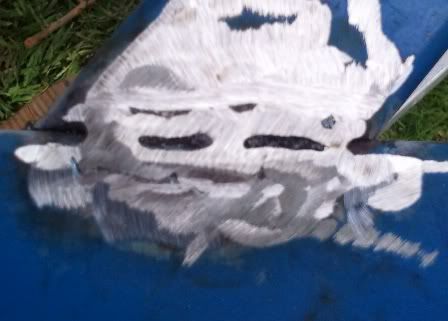 You can see that the butt weld has taken in places but there are voids where there is nothing holding the pieces together. I bought a cheap grinder because my De Walt was in the skate and I was concerned about stripping all the screws that held the grinder to the skate. I spent two days grinding and rewelding. I'd love to say that my welding would pass muster after building the table base, but the results of my redo efforts prove otherwise. A lot of welding and grinding away ensued. Every now and then I got lucky and produced a weld that looked as though it might hold: 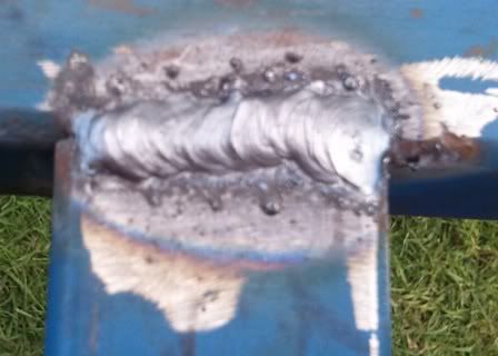 But you can see from the splatter that I still don't have the rod at the right distance for the power setting (and straight lines are a problem!). Anyway I eventually got the joins looking as though they would hold under vibration. I used a flap disk in the grinder to smooth welds and remove splatter. I degreased the ladders and set to painting. First a rust converter where there was surface rust that didn't come free with sanding and wire brushing. I read up on the attitudes on this site to fillng welding (i.e. don't do it) but figured Gerald hadn't head to deal with quite my quality of weldng I read up on fillers and figured that they just needed to have a similar expansion coefficient to steel and set hard. I had some microballoons in my shed (small glass spheres used as a filler in epoxy applications) and epoxy undercoat primer. I made a paste with these and used it to fill the worst of the unevenness.I primed the ladders and they look acceptable (this was never going to be a build of the quality displayed elsewhere on this site, mainly because of my inexperience with any kind of metalwork and construction, and partly because of my impatient nature). They'll do the job of holding the beams off the ground, parallel and level. Now to drill the beams for the chain support, prepare and paint the beams and paint everything blue and assemble and square up and the base should be done. At 4 months it must be one of the longest base builds on the site!
|
|
#104
Mon 27 December 2010, 05:04
|
|||
|
|||
|
Preparing rails for mounting
After a final couple of passes with 60 grit then 120 grit I declared the rail grinding done. I'm not painting the rails, but was unhappy with the flush of rust and discoloration that the wire brush and steel wool wouldn't clear. I was also worried about them rusting while I'm in Hawaii next week.
I read the instructions on my rust converter. It claimed that it could be used to polish up discoloration by rubbing on with a cloth or such and then drying off. It also claims to leave a finish that is proof against rust, so oiling is unnecessary. I went at the rails somewhat skeptically and used a pot scourer to apply the Ranex and remove promptly with a dry cloth. I was impressed with the results. The rust and discoloration did remove leaving the rails with a sticky coating that I hope will dry to a resistant finish. Painting Beams tomorrow. Then on to table assembly
|
|
#105
Tue 28 December 2010, 04:15
|
|||
|
|||
|
Paint Em Red
Hi Red
The product is a phosphoric acid, it reacts with the iron oxide to produce a black looking substance that is the combination of the iron oxide and phosphate ion. It will also sometimes leave a powdery white coating over the black stuff that you can then wipe off. This will convert the existing iron oxide in its tracks but will do nothing to stop the continued oxidation of the rest of the iron. After rust converting the only path to stop further rusting is to seal it quick and dirty with a coat of red oxide primer. Leave it at that if your are short on time or just don't want the hassle of a flashy paint job. As Neil Young pointed out - "Rust never sleeps" and unfortunately phosphoric acid will do little to arrest this process over the long term unless the steel is sealed. Regards Ross Last edited by Surfcnc; Tue 28 December 2010 at 04:16.. Reason: spelling
|
|
#106
Wed 29 December 2010, 00:18
|
|||
|
|||
|
Hi Ross,
Thanks for that info. I'll look at coating options. If they have to be painted, then they might as well be blue.
|
|
#107
Sun 16 January 2011, 16:14
|
|||
|
|||
|
More Rube Goldberg / Heath Robinson
I spent my days off over Christmas cleaning and painting. Then I went away to Kauai for a week (to give the paint a chance to cure
). I assembled the table this weekend. This took a bit of effort because the beams are so darn heavy. I bolted on the legs under the beams and then one cross ladder on each side. Now a hoist would have been the correct thing at this point. Not having one or access to one meant that I used a car jack to raise the beans to about 45 degrees (in stages, with bracing to support the weight at each lift and rope to hold the legs from sliding out. Once the beams were 3' off the ground and the legs on the ground then it was a quick lift by me and my 70 year old father in law (with a combined weight of 150kg or so!) to get them upright. The x-ladder provided a handy fulcrum and stabilised the assembly leaning slightly inwards once the beam was at the top. Then it was align the halves and bolt together. Now I have a table to built my gantry on  Photo to follow. Photo to follow.Now I'm not advocating the above as a method. If I was smart I would have followed the plans and raised the beams on trestles (the car jack could still have done the heavy work of lifting each end a few cm at a time, and a well clamped and supported beam or 2 would have prevented problems with topling. Then I could have slipped the y-ladder under, jacked it to height and bolted it in place. Sometimes you have to do it "the other way first" in order to learn! I then fitted some castors (I got steel wheels, 230kg capacity for $25 each from Bunnings, which seemed a bargain) so I could move the table from where it was assembled back under cover. In the process I decided that if I ever build another table it will mostly be welded. It's quicker and there's less mucking about trying to square things up again. Of course I might change my mind when I get to move this table again. Last edited by Red_boards; Sun 16 January 2011 at 16:15.. Reason: typos
|
|
#108
Wed 19 January 2011, 19:19
|
|||
|
|||
|
Here's the beast of a table - all 350kg or so of it!. Some scuffs and scratches in the paintwork from the assembly process. The light blue is fading caused by cutting oil when I drilled for the cable chain support. Had to remove the bottom bolt in the legs to fully raise the feet so that the wheels could contact. Will fix this by having the wheels closer to the ground.
 Judicious use of a scaffold pipe, car jack and several clamps got the table square. Support board in place and bolts tightened.
|
|
#109
Wed 19 January 2011, 21:50
|
|||
|
|||
|
Pinion problem solved
The wisdom on this site!
After reading here about suppliers boring out their standard pinions to custom diameters I went back to mine (TEA) and made the enquiry. They were able to supply 24 teeth with internal bore correct for the motor shafts. Best thing is that they charged about $7 per pinion to do the bores (total ~%15 each). Pinions arrived yesterday and slip neatly onto the motor shafts.
|
|
#110
Thu 20 January 2011, 19:36
|
|||
|
|||
|
Hi Red,
When I ordered my pinions from TEA, I requested for the bore to be machined out, obviously for extra costs, this is the reply....... "All items are ex stock. We do not offer machining to the spur gears to they come with their standard bore sizes as in the catalogue." I'm not fussed, I'll get machining done locally, just wondering how you went about it so that others who order from TEA can get the boring done there and not go though the drama as you did. Quadro
|
|
#111
Sun 30 January 2011, 16:51
|
|||
|
|||
|
That's interesting.
I just called them and ordered 24 pin with 14 mm bore and they quoted a price. I'm pretty sure there isn't this size bore in the catalogue, so they must have done it custom. You could try just asking for a bigger bore. Maybe it was ex stock, but I'm pretty sure they bored it for me.
|
|
#112
Sun 30 January 2011, 22:43
|
|||
|
|||
|
A mass (mess?) of clamps
Welded (more about that later) the Y-car together. My laser cut parts were pretty straight and flat. I tried to get everything squared up using magnets before any welding. I clamped it together to try to stop things distorting out of shape during initial tacks. I used threaded bar to hold the key parts parallel al la surfcnc's suggestion.
 One of the most frustrating things was getting the nuts onto the threaded bar. They were so tight I had to use a wrench the whole way. I did run the bar in my drill and put cutting paste on the bar, but there was a fair bit of manual screwing to be done, too. I think the galvanising had "grown" over the years I've had the bar unused. The bottom threaded bar was great to get the plate firmly seated against the base. I then used the top threaded bar to get the plates 90 degrees to the base and parallel. The clamps are pulling the base into contact with the laser cut flate base on the vertical ends. This did a good job of pulling out the 0.5mm or so of bow in the base plate. The welding. Oh the horror! Let's just say that I used a lot of welding rods, did a great deal of grinding and restarting, and even managed to burn the edge off the plate in some places! I'm seriously contemplating taking the gantry for a "proper" welding job elsewhere
|
|
#113
Sun 06 February 2011, 03:03
|
|||
|
|||
|
Rails drilled
I eventually got the Y-car welded up. It's been raining a bit in Melbourne so that slowed down my return to welding hell. I counted 7 rods used for welds K-S. Probably a MM record. Anyway the monocoque construction seems rigid and ready for paint.
Getting to the business end of the build - slowly progressing to those "A" (assembly) rated plans. Lots of small jobs to do which is great because I get to tick off a bunch of pages in the plans. Racks cut (I was lucky the supplier had 3m lengths so I didn't have to join shorter lengths for the X-axis). I'm using double sided tape only to attach them, so here's hoping. Pinions drilled and tapped. I don't know how other people held the pinions in place for drilling. The teeth seem pretty soft for clamping so I clamped a rack cut off to the drill table, located the pinion and then clamped another rack offcut across the top of the pinion. This gave a nice firm hold and protected the teeth. Gantry rails fitted (will be removed for welding) and y-car tested for fit and rolling. I don't have space for thin nuts on the vee bearing axles - the y-rails won't be wide enough apart (my thin nuts are about 8mm thick). X rails drilled. My setup is below. I used a cutoff of flat bar as a straight edge on the drill table so that the bit would hit the rail 46mm from angle edge. I set one end of the flat bar to 240mm (my inter-hole distance) from the drill centre. Then I lined up each successive hole in the rail from the last against the flat bar reference. I got through both 3m rails in under an hour and the last hole was spot on (60mm from the end) in both cases. 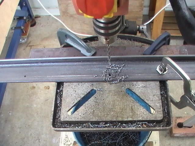 Now I have to build a 60cm high rolling table for the drill so that I can drill the beams for the x-rails. Mind you, I have wheels on the table, so I could move the table under the drill (if the floor was level  ) )
|
|
#114
Sun 06 February 2011, 05:56
|
|||
|
|||
|
Red that does not look right to me.
The 46mm dimension for the hole center is from the back of the angle. Yours look too far towards the front edge. So do not enlarge the holes until you have proven me wrong !! Regards Ross
|
|
#115
Sun 06 February 2011, 19:00
|
|||
|
|||
|
You've got a good eye. I put a caliper on the holes and got a hole center 46.5mm from the back of the angle.
The total width of the angle is 64.85mm. The distance from the scored line ( a secondary check) to the closest edge is 17mm. The hole centres are above the scored line by a mm. The holes are 7mm diameter. There may be a little parallax happening in the picture. Last edited by Red_boards; Sun 06 February 2011 at 19:07..
|
|
#116
Sun 06 February 2011, 21:39
|
|||
|
|||
|
Not that good, more than happy to be wrong on this one Red.
Cheers Ross
|
|
#117
Wed 16 February 2011, 19:57
|
|||
|
|||
|
Drilled and tapped the beams for x-rails
In order to drill the beams I first had to get my drill press mobile and up to the correct height. I mounted it on a small table screwed to a trolley I knocked up from wood scraps and wheels from a rolling office chair (I figure those castors must be rated ~150kg at least in order for larger people to sit on the chair - easily enough for my 70kg drill).
I did the beam drilling a little differently to the plan steps: After doing and redoing (and redoing) the calculations for how far to set the rails from the inside of the beam (~50mm, in my case - my beams are 88mm wide), I set one rail on the beam, clamped it straight it using a taut line as a reference along the rail edge and then, starting at the centre, worked to the ends drilling the beam using the rail as a jig. I drilled and tapped each hole, and put a bolt into each as a temporary hold to free up clamps. There wasn't any extra effort in tapping through the rail and beam at once. I lined the second rail off the first and set it to the correct width using 4 wood jigs. I started at one end and drilled, tapped and bolted as I went along and checking the rail was pushed against the wood jigs. I don't have a sufficiently accurate tool to measure variation in the rail distance apart. I can't pick up on it using a tape measure (i.e. it's under 0.2mm over the 1701mm width). Lastly, I know I need to take the rails off and bore the holes out to 12mm and then refit. But is there reason to do this if the rails are parallel as they stand? Is there a case for now shimming them level?
|
|
#118
Thu 17 February 2011, 04:07
|
|||
|
|||
|
Red - a tapped hole through two pieces of metal is not the same as a through hole and a tapped hole.
Ever driven a screw though two bits of wood undrilled, some times they actually lift apart rather than screw tightly together. A clearanced hole through to a tapped hole will clamp the top piece down tight to the bottom piece every time. Under your current circumstances with the two tapped holes above each other, the fine adjustment for rail height is unlikely to be achieved. You have not engineered a clamping mechanism. Conceptually it is a mechanism that will hold the two components apart at a set distance. It is not a good idea to deviate from the plans unless you are certain of the consequences. As you are asking the question, I am certain your NOT certain. Regards Ross
|
|
#119
Thu 17 February 2011, 15:43
|
|||
|
|||
|
Thanks. That's the sort of input I was interested in, and why I asked the question.
|
|
#120
Thu 07 April 2011, 18:43
|
|||
|
|||
|
A bit of a hiatus, I'm getting back to finishing it.
I spent a week here: http://www.surfcoastnews.com.au/2011...d-titles-2011/ And the weeks before repairing my favourite surfboard that I snapped in a contest two weeks before the world's. Vaccuum bags, late nights watching epoxy resin cure and early mornings sanding away. I simultaneously designed and got a new board cut on a CNC machine and completed as a back up. Busy couple of weeks! Anyway the repair ended up OK and I rode the repaired board and ended up with 3rd in the over 50's. On the MM, I subbed out the gantry because my welding has not improved and I wanted it to end up square. $220 seems worth it. I sealed up the holes I drilled in the wrong places in the Z-car and revised those. I got bearing supports in the post from MetalHead Mike. This was cheaper than local shops were prepared to do them for. Pics to follow. Now to checking whether things roll, painting the bits and bolting together. I'm shooting for a MM number under 100, so I'd better finish by my June deadline.
|
 |
|
|
 Similar Threads
|
||||
| Thread | Thread Starter | Forum | Replies | Last Post |
| Making Skins #74 - Brisbane Australia | Surfcnc | MechMates already cutting | 1078 | Sun 20 September 2015 11:05 |
| A chip off the old block | quadtech | Miscellaneous / General / Whatever / Catchall | 0 | Tue 23 August 2011 07:30 |
| Anyone need more bearings? MELBOURNE | rotorzoomer | The Market Place | 1 | Fri 12 February 2010 06:45 |
| M1 18 000 Alternative Stopper Block | dmoore | 20. Gantry | 15 | Fri 13 June 2008 12:47 |
| Rail and Block | John | Archives | 2 | Mon 09 April 2007 15:25 |


